Friday, November 23, 2007

Alignment

I think I need to describe how I'm using the jig to align the frame. It starts at the rear axle which is held by spacer blocks that hold it at 2" centered above the jig surface perpendicular to the centerline and level. I then use two spacer blocks to hold the maintube at 2.707" above the jig with side wings that hold it centered. I then just clamp the sidewings to clamp the tube.


The next step is to align the maintube so the headtube is perfectly vertical. To do this I use a piece of straight 5/8" rod. I then made a set of spacers for it by drilling a hole through a piece of wood and mounting it on the rod and turning it in the metal lathe. I made two spacers that press fit into the headtube out of oak to hold the rod. And a third out of pine that is exactly 2" in diameter as a reference at the top of the tube.


I locate the tube front to back by locating the front of the 5/8" rod at a mark I made on the jig. I rotate the tube to align it vertically by using a square and sliding it against the tube and then sweeping it back and forth against the spacer at the top of the rod so it scrapes evenly on both sides. I now know that I'm aligned to within a couple thou.


Wednesday, November 21, 2007

Yay! Headtube!

So I have to say that nova rocks. I ordered a new HT on Friday, I was expecting it to take a week with the holiday and all. I got it on Monday! So yesterday I cut it to length, cut the hole in the frame, and brazed it in place. I am MUCH happier with the brazing on this one. I didn't cook the tube nearly as much. There is very little charred flux (as you can see on the first image). The cleaned up shot is just after hitting it with a wire wheel on the angle grinder. I think I'll leave it like that. I'm no pro yet, but I'm pretty happy with that braze.


I also brazed in the seat mounts and the rear cap plate the other day. The seat mounts got good penetration, I'm quite happy with them. There are a few slightly dry edges, but I'm confident I got good penetration deeper into the joint, I just should have pushed the brass in more all the way round. I was trying to be too tricky by pushing it at only the top and bottom and using the heat to pull it around. On the whole this worked pretty well, but I missed a few spots.


This is the cap at the end of the maintube. I just slip brazed it as it's only moderately structural. It provides some protection against collapsing the tube, but that shouldn't require much and a thin slip braze should be sufficient. I also think I built up a good inside fillet. I put a lot of brass into this joint and not much was left outside. I didn't lose any to the floor, so it has to be somewhere.


Tuesday, November 20, 2007

Things left to do

Time to step back and put my thoughts in order. Here are the tasks I have left to do and some rough estimates on how long it's going to take me. These estimates are pretty rough, but I'm getting better at estimating my time.

  • Fit headtube - 4 hours
    1. Rough cut frame with Dremel cutoff wheel
    2. smooth out frame with Dremel drum
    3. Final fit with die grinder and possibly file
    4. Cut HT to length with lathe (2 cuts)
    5. Mark HT for placement
    6. Braze in HT
    7. cleanup
  • Fit FD mount - 5 hours
    1. Design miter on DeltaCad
    2. Mark tube
    3. Cut tube & test fit
    4. mount AL box tube alignment piece
    5. Final fit tube
    6. make end-cap
    7. cut tube to length
    8. braze end-cap
    9. mount tube to alignment piece
    10. tack braze
    11. finish braze
    12. cleanup
  • Align tube on jig - 1/2 hour
  • Braze BB - 3 hours
    1. make clamp from scraps of tubing, angle and rods
    2. test fit alignment
    3. make spacer piece
    4. tack
    5. finish braze
    6. cleanup
  • make rear-stay connecting pieces - 2 hours
    1. mark out
    2. drill
    3. rough cut
    4. finish grind/file
    5. tap(?)
  • make lower seat stays - 3 hours
    1. drill relief hole
    2. drill out stay
    3. cut to length
    4. cut end slot for dropout
    5. fit dropout
    6. braze dropout
    7. fit pinch bolt
    8. braze pinch bolt
    9. cut slot
    10. cleanup braze
  • finish chainstays - 4 hours
    1. clamp to maintube
    2. fit lower seat stay connecting piece
    3. braze lower SS connecting piece
    4. tack braze to maintube
    5. finish braze to maintube
    6. cleanup
  • Fit brake bosses - 3 hours
    1. make jig
    2. mount bosses in jig
    3. braze
    4. cleanup
  • Fit cable guides - 4 hours
    1. make helper clamp
    2. plan out cable runs
    3. locate and mark locations
    4. clamp and braze for each
    5. cleanup
That should be about it for the frame. There are a few other tasks like the seat mounting plates and the tops of the seat stays. Not to mention paint. But that gets me pretty much done with the steel work. Total estimate is 28.5 hours remaining. I should be able to get this done by around Christmas, which would be a good thing. I should have it on the road, weather and finances permitting, sometime in February.

Sunday, November 18, 2007

Starting over...

In an earlier post I mentioned how my unwise use of a dremel tool with a burr caused a few nicks in the tubing around the seat mounts. Initially I wasn't worried about this, but the more I thought about it, the more it bothered me. I'm worried about stress risers and the loss of strength caused by the thinning of the tube. I ran some numbers based on assuming that the rest of the bike was perfectly rigid (obviously false) and hitting a 2" bump at 50 mph. Granted this was not an FEA approach or anything so sophisticated but it should give a nice upper bound.

I found that the maximum stress was right at the seat mount (no big shock there) and with the full wall thickness I was right at the limit of 4130 steel. Thinning the wall by .005" increased the stress by close to 200MPa which is WAY over the limit. Now I realize that these numbers are way high since it assumes that the rest of the bike is totally rigid, when in fact the tires take up a lot, the fork flexes, the wheel deforms slightly, etc. All of the above dramatically reduce the maximum stress. What the numbers do tell me is how much relative strength is lost by thinning the walls at that location.

Because of this I decided to put that frame aside and start on a new piece of tubing. Realistically the original would probably never fail, but this is my first frame and I just don't have the experience to make that call. I might finish the original frame yet for someone lighter and/or less aggressive than me. 50mph downhills are an everyday part of my commute.

The good thing about all of this is that I still have several pieces of tubing left and the only thing I needed to re-order was the headtube. I took the day off work on Friday and spent some time working on the bike. I am basically back up to my stopping point on the first frame. I'll go over the details in future posts.

Tuesday, November 13, 2007

Head Tube and Rear Fork progress

I made a lot more progress in the last week. Again time has been short, but I got another good day in last weekend and have been getting more efficient otherwise. Overall I'm getting pretty good at joint cleanup and metal shaping. The head tube joint is VERY good, no wiggle at all. The BB is quite tight. It's perfectly parallel with the maintube and within about a degree on rotation just on the initial fitting. I'll sort out the rotation error when I do the final fit, but that's remarkably good for a first effort IMHO.


The thing I need the most work on is brazing. The joints are turning out ok, but not stellar. I roasted the headtube a bit. Note the charred flux. I'm pretty happy with the rear dropout brazing actually. I got really good penetration. I ran a larger tip on the torch and that helped quite a bit. I definitely ran it hotter than the previous joints, but it went MUCH faster, so I'm satisfied with the results. I'm not worried about the HT brazing since it's such an inherently strong configuration. I probably could have tacked it and it would have been more than strong enough.


I had a really cool setup for aligning and brazing the rear dropouts but the camera batteries were dead that day so I didn't get any photos. The Breezer dropouts I used were harder to use than I had thought. They look like they are cylindrical in cross section but they are actually slightly conical. I fitted them by clamping both legs to a board so that the ends were close together and filing them evenly. But I had to do a lot of dremel work to fit the conical section of the dropouts.


To align the rearfork, I first made a false axle supported between two wood blocks. I used a 3/8" rod for the false axle and carefully aligned it perpendicular to the maintube with the fixed nuts set at 135mm apart. I then made wood offset blocks to hold up the maintube at a fixed dimension (2.707") above the plane of the jig. I used a scrap of 2.5" AL tubing to center the ends of the rearfork on the maintube. To miter them, I'm going to use either a laser or just a pencil to scribe around the maintube onto the rearfork arms. I'll need to mount the maintube temporarily behind the rearfork connection to scribe the back. I still need to clamp everything in place. These pics are just a preliminary fit.


I should explain the piece of 5/8" tube running through the headtube. It's held in place with press-fit wood spacers that I turned on the metal-lathe to keep it centered. The cylinder on the end is turned to the same diameter as the width of the BB shell. I will also turn one that is 2" diameter the same as the maintube. By mounting this and then squaring it to the jig, I can ensure that the headtube is perpendicular to the rearfork within good tolerances. I can also use the 68mm one to ensure that the BB is square. I'll post more pics of the technique as I get to it.

Monday, November 5, 2007

Progress!

I've made a lot of progress in the last couple days. I did nothing for over a week but I got a good day of work in on Sunday. I have more than just this post, but I need to take more pictures so I'll post them up soon.

In short, I laid out everything on the maintube, cut all the holes, and brazed in the seat mounting nuts.

Tube laid out with cutting templates

Laying out the maintube

I printed out the cutting templates I created with my little DeltaCad macro. I first scribed a line on the maintube. Then I put on the BB template carefully aligned on the scribe. I then measured off an offset from a mark on the template and scribed a mark on the longitudinal scribe line to align my HT template with. Wash, rinse repeat.

I should note that I forgot to make a template at first for the end cutoff and the angled cut at the bottom of the BB, so I had to retrofit those later working from the existing marks.

Head Tube template marked with center punch

Head Tube cutout marked with center punch

To mark the cut lines, I used an automatic center punch through the paper templates, and then cut the templates off. This proved to work VERY well. The marks are easy to see and follow, and give visible feedback as you file/grind the finished miters. As you approach the punch mark, you can see little divots growing on the filed edge. it proved to be easy to get a PERFECT fit for the headtube.


BB template marked with center punch

Bottom Bracket

I marked out the BB hole the same way as the head tube. Here you can really see the utility of a marking template. Because the BB is off center, the hole doesn't look like a slightly elongated circle, but rather a figure 8. I didn't think of adding in the lower angled cut portion of the cut to this template, so after this was marked, I made a new template that just had the angled line on it, cut it carefully to the line, put the template on, and slid it up the tube until it was tangent with the front marks of the BB cut. This worked very well. The finished cut, which I'll post later, looks a bit like a boar's mouth with tusks.


Brazed in seat mount

Seat mount cleaned up

seat mount cleaned up more

Seat mounting nut

For the seat mounting I am using a brazed in nut and slotted plate arrangement a la Volae. The nuts I'm using are weld nuts from McMaster Carr. They have 6mm threading and are 14mm long. The OD of the barrel is about 7.5mm. After I center punched the holes for the weld nuts, I drilled the holes out on the drill press first using a small bit, and then a 5/16" (I think) bit. I then used a countersink to chamfer the holes since the weld nuts have a slightly rounded transition. The nuts were a tight fit in the holes, which is a good thing.

To hold them in place while brazing I used a piece of 6mm stainless steel threaded rod run from left to right through both nuts. The rod was removed between brazes, but you get the idea. This worked well except for the 3rd braze where the rod got stuck in the nut. I suspect some flux got in the threads. I tore a few threads off the end of the rod, but was fortunately able to save the nut by drilling and tapping it. If I had to do it again, I'd run the rod in from below, and put a bolt in from above to keep the threads clean before fluxing. Brass doesn't stick to stainless so that should be safe (and is how I did it for the 4th nut)

To clean up the brazes I started with a flat file, but that wasn't real great. I tried using a dental burr which seemed to work well but made my hand numb after a while. I also realized that I had nicked the tube in a few spots, you can see these in the last pic. They aren't as bad as they look in the pic but they are bad enough I can't sand them out easily. I don't think they will be a structural concern but they annoy me. Ah well, it's my first frame, live and learn. I later switched to using a small but aggressive cutting half round file for cleanup. I like it much better.

Wednesday, October 31, 2007

Tube Miter Software

Giles Puckett wrote a nice little windows app some years ago called tubemiter that will plot out a curve on a piece of paper that you then wrap around a tube to act as a cutting guide. This is a great idea, only his application is limited because A) it doesn't allow for tubes that meet with an offset (i.e. the center axis of the two cylinders don't intersect). And B) it only prints the end miter, it's up to you to figure out how to align it.

I'd like to extend his application by adding more reference lines, an offset parameter, and possibly even the ability to put multiple miters on a single printout to minimize compounding errors from measurement. If I could plot out both my headtube and BB intersections, and print it on an 11x17 piece of paper, that would be awesome.

Instead of using a standalone windows application, I decided that the best bang for the buck would come by writing a script for my favored CAD program, DeltaCad. By using a CAD program rather than a standalone app, I can dimension and draw in other references as needed. I can also plot multiple intersections and cut and paste them onto my final drawing. The only drawback to this approach is that the macro runner is a bit flaky when run out of wine under linux, such is life I suppose.

I should point out that modifying the script to work with elliptical tubing would be pretty trivial. If anyone is interested I'd be happy to make the changes.

You can download a demo copy of DeltaCad from the website, and a copy of my script here. To run it, go to the macro tab. Click "Edit macro list" and add the tubemiter file to the list. Then select it from the pulldown and select run macro.

Thursday, October 25, 2007

Stuff I need to Order

This is a list of stuff I need to order to actually continue to make any progress on the bike. Hard to make things when you don't have the materials...

From Nova:
  • Head Tube
  • BB shell
  • 10x cable stops
  • breezer dropouts (with boss)
  • MTB fork blades (29er)
  • 4 Pinch bolts
  • canti bosses (max offset)
From Atom:
  • Seat
From Online Metals:
  • 20ga flat sheet
  • Square tube (for idler mount)
  • 6" 5/8" x .065" tubing
  • 2' 1.125" x .065" Aluminum 6061 -T6
From McMaster-Carr:
  • Weld nuts (90563A640)
  • silver brazing alloy (??) (76955A72)
  • silver flux (black, white?)
  • 6mm SS bolt (for fixturing) (92000A450)
  • 6mm SS socket head bolt (91292A141)
  • 8mm SS socket head bolt (for idler axle) (92290A461)
  • 8x10mm bushing for idler bearing holder (6679K13) (might need 10mm version)

Wednesday, October 24, 2007

To-Do List

I find it helpful to write down all the things I need to accomplish from time to time just to wrap my head around what's coming and to sort out the places I need to understand better. This includes what needs done, as well as any points on how to do it that I've thought of.

Things I need to do in order to get the maintube, HT, and BB brazed up. (I'll do rear fork and finishing steps, seat mounting, sprint stays, etc. later)

  • Level jig on saw horses
  • Decide if I am brazing FD mount along with everything else or later separately, and what size tubing I'm using for it.
    • machine appropriate spacer blocks
    • figure out how to miter the thing.
  • Prepare jig
    • Draw out maintube, head tube and BB locations on jig (FD mount?)
    • mount spacer blocks
    • machine wooden square blocks for angle alignment brackets and mount
    • Drill and prepare for BB fixing bolt
  • Mark out maintube
    • Mark 90 deg longitudinal lines on maintube
    • Mark intersections for headtube, BB, and seat mounting penetrations
    • Print out tube miters for HT and BB penetrations, align with longitudinal lines, transfer to tube with centerpunch and marker.
  • Prepare HT
    • Use cutoff tool on lathe to cut partway through tube to mark accurate square cutoff for cutting to length later with hacksaw/file (post brazing)
    • drill breather holes
    • mark intersection with maintube for positioning purposes
  • Cut maintube
    • Cut out headtube penetration.
      • start with dremel
      • clean up to marked line with 1" drum in die grinder
      • Test fit in jig, wash rinse repeat
    • Cut out BB penetration
      • hacksaw lower bevel & rough out
      • finish with 10" half round file and 1" drum
      • Test fit
  • Cut and fit plate for lower bevel under BB
  • Cut and fit FD mount
  • Drill holes for seat mount
    • This is important to do before any brazing since I am doing it on the mill and any brazing material could throw it off depending on exactly how I mount it
  • Mount HT, BB, lower bevel plate in jig.
  • spot braze LH side of headtube, and Top and Bottom of BB (braze both LBP and BB )
  • Take frame out of jig and flip over
  • remount (if this is hard, something warped)
  • braze RH side of ht
  • take frame out of jig, mount in frame stand and finish braze all joints.
  • aligning and brazing seat mounts: (assuming working on LH side)
    • start by running a SS bolt all the way through from the RH side of the frame so that the nuts are tight but it only contacts the first couple threads on the LH nut
    • mount a piece of AL flat stock to the LH nut using a short bolt
    • sight along the maintube and ensure that the flat stock is parallel with HT, also measure with square.
    • adjust as needed
    • carefully remove flat stock without shifting nut
    • braze in nut
    • repeat for other side

Sunday, October 21, 2007

Steering Geometry

In spite of the fact that the modern bicycle has been around for considerably over a century and even the recumbent bicycle for over 80 years, understanding bicycle steering is a persistently difficult problem in dynamics.

Contrary to popular belief, gyroscopic forces play only a minimal role in determining 2 wheel vehicle stability. Check out this site for a whole bunch of interesting experiments with counter spinning wheels and interesting steering geometries.

Another bit of required reading is David Jones' classic treatise on bicycle stability in which he attempts to build unridable bikes.

For this subject and just about everything else related to bicycle technology, check out Bicycling Science.

Finally for a good, relatively concise writeup on the dynamics of 2 wheel vehicles , check out this wikipedia article.

Boiling down the above, there are really 3 variables that we can vary with our design.
The combination of the above give us:
The difference between mechanical trail and trail seems subtle, and in fact it is, but Jim Papadopoulos makes the case in bicycling science that MT is a more relevant measurement of how the bike actually handles. It represents the lever arm through which the perpendicular component of the vertical support force acts. In other words it is the lever length that forces the wheel to turn in the direction of a turn when you lean the bike. It's also interesting to note that two bicycles which have the same T may have a very different MT due to differences in head tube angle.

Having said all that, increasing T and MT all other things being equal will cause the bike to be more stable. Stability is a bit of a loaded term since it is usually used in the above mentioned documentations to discuss the ridabilty of a bicycle hands-free. For my purposes however I'm considering a more subjective view. A "stable" bike is one that feels like it is "on rails" and wants to hold it's line. An unstable bike is one that is lively feeling and handles quickly. The best handling bikes are compromises between the two. It would be easy to make a bike so stable that it was practically impossible to knock over once at speed. Unfortunately it would also be so stable that swerving to avoid that car or pothole would be equally impossible.

For my particular design I'm starting with an existing fork. It's a kinesis 650C Aluminum Tri fork. It's light, good quality, and fits the 559 wheel size adequately with either long reach brakes or some creativity. I measured the rake on this fork to be 34.54mm, and it's axle to crown length is 340.36mm. I'm also decided on using 559 rims with 25mm tires for the purposes of this design. If I ever want to use wider tires (for touring for example) I'll need to make a new fork anyway since this one won't clear wide tires. At that point I'll simply optimize it's rake for the new wheel size.

Since I have 2 of my variables fixed already by deciding on a fork and a wheel size, I need only to decide on head tube angle. The first thing I did on my drawing was to draw in the fork rake by drawing a circle with radius 34.54 centered on the front axle. Then for the heck of it I drew in case where the headtube was simply perpendicular to the maintube. This is the maroon line. This gives me a headtube angle of about 71.3, T of 68.61 and MT of 65. These T and MT numbers are very high. The highest MT listed in a table of common values in Bicycling Science (Table 8.1, p274 of Third ed) is 58.5, and the highest T's are 76.2 and 69.8, but both are found on track bikes. This does however put it close to the Bacchetta Aero, which is obviously a successful design.

I am still uncomfortable with the very high MT and T numbers so I decided to see what I would get if I fixed the trail at 60mm. This is a good common number for a stable touring (or similar) bike. This is the blue line. I get a HTA of 72.8 and a MT of 57.32. These are still on the stable end of normal, but they are much more inline with what is out there in the upright world. This also puts my trail nicely between the 70's of the Aero and the 50mm of the Volae Team.

Friday, October 19, 2007

Drawing the Frame in CAD

We now have all the info we need to draw up the frame in CAD. To recap we are going to use the following values: (SR = seat reference mark)

SR above ground = 609.6mm (24")
C of G behind SR = 39.7mm
BB center above SR = 228.6mm (9")
BB center in front of SR = 783mm
Heel Clearance = 75mm

FYI the CAD program I'm using is a nice shareware program called DeltaCAD. It's pretty easy to use and I've gotten used to it's quirks. There are more featured apps out there, but familiarity is worth more than features in this case. It's a windows app but runs well under wine on linux.

Step 1:
Draw a horizontal line that is 2000mm long. Then in the center draw a vertical line that is 1000mm tall. The horizontal line is the groundline and the vertical line is the center of gravity.

Step 2:
Draw a vertical line that is 609.6mm tall, 39.7mm in front of the C of G. This represents the SR. Then draw a second vertical line that is 609.60 + 228.6 = 838.20 mm tall, 783mm in front of the SR. This is the BB center.

Step 3:

Now we need to know the wheel dimensions. We are going to use conventional 26" mtb wheels, but with narrow, 25mm tires. To get the outer diameter of the finished wheel, you take the bead seat diameter of the wheel, 559mm for us. Add 13mm for the bead height, then divide by 2 to get the radius and add the tire dimension (25mm). So we get (559+13)/2 + 25 = 311mm.


Draw a horizontal line 311 mm above the ground line.

We now need to find the front axle location. To do this we will need the heel clearance dimension which is 75mm. I've defined this as the distance between the arc defined by a 175mm crank and the top of the tire. But in this case we really want to find the distance that is 175mm + heel clearance + wheel radius = 175 + 75+ 311 = 561mm away from the BB center. Draw a circle with this radius and mark on the axle line where it intersects. This is the front axle location.

Step 4:

Draw in the wheel and measure the distance from the c of g line. In this case it is 630.92mm. We will use this in the next step.

Step 5:

Now that we have the front axle distance from the c of g, we can find the location of the rear axle. But first we need to decide on the weight distribution. I said previously I want between 45 and 50% on the front wheel. So I'm arbitrarily deciding on 48%. Now we need to solve for the wheelbase. 630.92 = (100%-48%)*wheelbase. Wheelbase = 1213.31. Mark out the rear axle location 1213.31mm from the front axle and draw in the wheel.

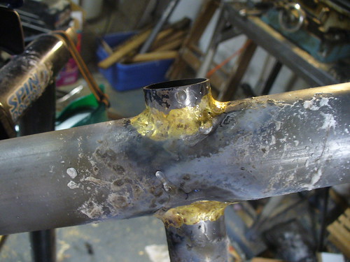
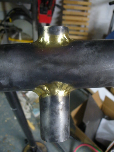
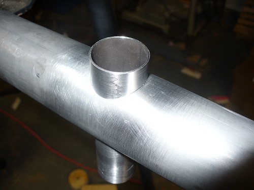
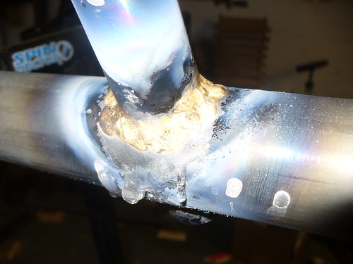
Step 6:

We are going to braze in the BB for this bike off center so that the top edge of the BB shell is a the same level as the top of the maintube. This give us better front derailleur clearance. So I took a look at Nova cycles and found this BB shell. It has an OD of 31.8mm so we draw a circle of that diameter centered on the BB center.

We then need to ensure that the maintube clears the seat. Conveniently we used the low point of the seat for the SR, so we just need to account for the thickness of the seat and a little extra. The seat I am considering is wood, and is ~3/8" thick. So I gave 15mm of clearance. I draw a circle with r=15 centered on the SR.

Then draw a line that is tangent to both circles and ends at the rear tire (we'll shorten it later). This is the top edge of the maintube.

Step 7:

Finally draw a parallel line that is 50.8mm below the top line of the maintube, then draw a longer parallel line that is halfway between them that extends to the rear axle. Mark the offset from the axle.

So far so good! The wheelbase looks good as does the rear axle offset. Next time I'll talk about steering geometry.


BB to Seat Distance Measurement

This is pretty simple. I again took my mockup seat and this time just placed it facing the wall. I put a mark on the wall with masking tape that is the right height above the seat base to represent the pedal when the crank arm is horizontal. In my case, as discussed previously, this would be 9" above the seat reference.


I then put on my cycling shoes, sat in the seat, put my heels on the mark and pushed myself backwards. Then fine tuned it a hair to get the leg bend that seemed right when my cleats were on the mark. For me the distance from the wall to my seat reference was 96.3cm. I use Time ATAC pedals which have a stack height of about 1cm (not including the cleat here). And I'll probably be using 170mm cranks. So my actual BB center is 96.3 - 17 - 1 = 78.3cm in front of my seat reference.

Interestingly when I get my new, real, seat I can use this same method to figure out where the seat reference is. I'll prop the seat up at 28 deg from horizontal and push away from the wall the right distance, measure 96.3cm, draw my mark, and there we go.

Weight Distribution

As I discussed in the last post, I am trying to optimize weight distribution for this bike. To that end I need to know where my center of gravity is when in riding position, or at least where a vertical line that passes through my C of G is. I'm not going to worry about the weight distribution of the bike itself since that would add a huge amount of complexity to the process (without actually having the bike yet) and really it would only change the result by a pound or 2 in either direction which isn't enough to matter.

To do this I basically took a mockup bent seat I built previously that is set at 28deg from horizontal when sitting on a flat surface. I put it on a pair of 2x4's that were supported at the ends by a bathroom scale on one end and some scrap on the other to make it level. I put it roughly in the middle but just marked it so it's position is known. I then took 3 sets of readings 1 each with me on the contraption and with me off of it. I then swapped the scale to the other end and did another set of readings. Here is a link to my raw data.


As you can see I had some help with this. Also the living room is not really as much of a disaster as it looks in the pics. I swear!


Looking at the data. We take the average of the loaded measurements and subtract off the average of the unloaded measurements for both front and back respectively. This gives us 102.33 lbs on the front and 81.66 lbs on the back. So 55.62% of the weight was on the front. The 2x4's were 206cm between the measurement points. So to calculate the c of g, we take (100%-55.62%) * 206cm = 91.42cm which is the distance the c of g is from the front of the 2x4. We also know that the seat reference mark was 87.45cm from the front. So my C of G is 91.42-87.45 = 3.97cm behind the seat reference mark. Good to know!

Factors in Frame Design

The type of frame I am building is pretty simple, but there are still a number of factors to consider. Many of these techniques would be applicable to building any recumbent. Some of the factors will be inputs into the design and some will be outputs. Because I am building my first frame, I am considering the existing work that is out there, particularly from Volae and Bacchetta, with the expectation that if I am near them in terms of geometry, I'll have something that works. Having said that I am designing this frame from scratch and thinking about all the trade offs.

Lets look at the factors in detail:

  • Weight Distribution: I'd like to design this bike so that between 45 and 50% of the total weight is carried on the front wheel. Equal weight distribution is rumored to be nearly optimal in terms of handling. I don't know this from experience but it sure sounds good on paper so I'll go with it as a design criteria. In order to figure this out we need to find our center of gravity, which is dependent on several other things.
  • Seat Angle: I need to consider seat angle in order to calculate my center of gravity. I've fixed this for the purposes of this process at 28 deg from horizontal. I built a mockup seat that I could change the angle of and found that to be a comfortable angle for me. Using the same seat that will ultimately be used on the bike would be better, but I don't have it yet.
  • Seat Reference: The next thing to consider is where we are measuring the seat from. I decided to use the lowest point of the seat as my reference. I will be able to transfer this to the final seat I use later.
  • Bottom Bracket Height: This is calculated relative to seat height and it's something I don't have a good way to calculate. I could let it be an output of the process and optimize some other variables... but I decided it's easier to just pick a number and design around it. In this case I just copied the bacchetta aero dimension of ~9"
  • Wheelbase: This will be an output of the process in my case. I'm not going in with any preconceived notions of what it should be other than to say it should be in the same ballpark as the common highracers on the market. For reference the Aero is in the range of 1240mm and the Volae Team is around 1195mm.
  • Seat Height: I wish I could say that I arrived at this through some clever method, but really I just looked at what is out there and picked 24". That's in between the Bacchetta Aero which is around 23" and the Volae Expedition which is around 25".
  • Distance from BB to Seat Reference: AKA leg length. This was determined experimentally using a method I'll describe in a later post. It's a very important measure if I want to optimize weight distribution since I'm going with a sliding seat type of build. Using an adjustable boom would make this less important but would be more complex in other areas.
  • Steering Geometry: This really deserves a whole post of it's own so I'll pretty much say that what I'm going for is something between the Aero and the Volae bikes in terms of geometry. The trail is the most meaningful number when describing different geometries (all other things being similar). For reference the Aero has a trail of 71.5mm and the Volae Team has a trail of 50mm. Taken in a vacuum this would suggest that the Aero is more stable almost to the point of being dead while the Volae is a bit quicker steering. Overall I'd favor stability but I'll probably bring the trail in a little in my design. I'm going to let this mostly be an output however as long as it's within "normal" ranges.
  • Heel Clearance: I've defined this as the distance between the arc defined by the pedal spindle on a 175mm crank and the top of the front tire. This is not a standard definition AFAIK but it's easy to measure from pictures and works well for designing in CAD. For reference the Aero has a HC of 60mm and the Team of 86mm. I split the difference and rounded up a little and decided to go with 75mm. Again, this is something that only experience will tell me what works well, and I don't have experience so I'll just guess but keep it within established ranges.

Frame jig construction


This is pretty simple. It's a piece of 2cm MDF with stiffeners screwed and glued to the underside.

The whole thing is about 6.5' long x 16" wide. It's within about .005" of flat (according to my level) Good enough. I used one of the factory edges of the MDF as a routing guide with a pattern bit to straighten the long stiffener pieces. I cut out the cross pieces on the mill, but the same router technique could have been used there.

Thursday, October 18, 2007

Brazing Experiments

Last weekend I finally got the oxygen bottle to go with the torch I picked up on ebay some weeks ago. I am using propane driven with an acetlyene regulator after some reading on the framebuilders list that this is a safe and reasonable option. The whole kit cost me only about $180 including shipping but not including the propane since I already had the bottle on my grill.


I had also ordered some 1" x .035" wall tubing from Aircraft Spruce to practice on. Overall I'm very happy with the results. Even my first braze had reasonable penetration and draw through the joint. I brazed up my second and third joints in a sort of drunken H and tried to break them and was unable to. I twisted and mashed the tubing all to hell and even bent the heavy wall 3/4" steel pipe I was using to try to bend it with, but the joints didn't budge.

I also cut apart my 1st and 4th attempts to look at the penetration and overall fillet quality. I'm not saying I'm anything like a pro yet, but what I did on my first few attempts would have easily held a bike together and even looked reasonably good with a bit of cleanup. That's good enough for me for this project.


Recumbent project


For several years now I've been wanting to build a recumbent bike. Perhaps it's my inner geek showing through, but they just strike me as an inherently better platform for long distance, on-road touring and endurance riding. Recently I've been having upper back problems which have further encouraged the idea.

The style I'm interested in is a high-racer in the Volae or Bacchetta model. To my inexperienced eyes this type of bike has several advantages overall and several specific to the home builder.

Highracers use common sizes of wheels and thus gearing which makes finding parts easier, particularly out in the middle of nowhere. I can pick up MTB wheels at nearly any bike shop in the world. Other sizes may be more hit or miss. They have an aerodynamic position which is superior to most unfaired bikes of any stripe with the exception of low racers. However they put your head height near that of most cars which is better for riding in heavy traffic. They are also more "normal" looking somehow. Due to the higher rider height, they play nicer with riders on conventional diamond frame bikes than most recumbents.

Specific to the homebuilder, the main frame is nothing more than a straight piece of .035" wall 2" diameter cromoly tubing. The rear fork is comprised of common MTB fork blades. The rest of the frame is all common frame builder parts. There is no tube bending required or other complex techniques. The jigging for the frame can be quite simple. The fork presents a slight problem in that you are restricted to either tight clearance 650C tri forks which limit tire choice, or MTB forks which are way overkill on clearances. There are other choices, but the two I listed are the most common and cheapest.

Material is something I pondered for a long time. Carbon fiber is a reasonable option and a number of homebuilders have used it to make beautiful bikes. Jim Scozzafava has made some bikes that are the equal of many production bikes costing many thousands of dollars. I also tossed around the idea of an Aluminum carbon hybrid with AL tubes and wrapped carbon lugs. But in the end I settled on fillet brazed steel. I thought about using my mig welder, but I wasn't able to get good enough welds on the thin tubing to satisfy my inner perfectionist.

Steel has a few advantages. First it's relatively cheap and commonly available. It's also reasonably forgiving of mistakes. The biggest factor to me is that I am reasonably sure I can make a durable and long lasting bike from steel. I am not as sure with any of the other materials. There are also a lot of frame parts readily available for steel frames. The same cannot be said for carbon. This isn't a huge issue, but each little thing I need to make myself adds time and effort.

Seats, mounting, stay construction, idlers, steering mast and handlebars, etc are all things I've thought about a lot, but those will have to wait for later posts.

Wednesday, October 17, 2007

First Post


My goal for this blog is to be a repository for all the bikish stuff I do. Building, riding, whatever. Not much of a mission statement I guess, but it's all I got.